308QV Conversion to 358RR
Ferrari 308 2-valve models with Bosch CIS fuel injection represented the nadir of the 308 series performance starting in 1980. In 1983, Ferrari came out with the QV model (4-valve).The power of this engine brought the performance back up to the levels of 1975 (GT4); so much for progress! The only real performance increase came in 1985 when Ferrari released the 328 model displacing 3.2L. Finally, more power and torque. Our project goal was to take a 308 QV engine the next step beyond the 328. It is well know that the chassis of the 308 is a good platform for more power. The concept with this project was to make more power by increasing the displacement, but retaining the CIS fuel injection/Marelli ignition.
 Ferrari 308 2-valve models with Bosch CIS fuel injection represented the nadir of the 308 series performance starting in 1980. In 1983, Ferrari came out with the QV model (4-valve).The power of this engine brought the performance back up to the levels of 1975 (GT4); so much for progress! The only real performance increase came in 1985 when Ferrari released the 328 model displacing 3.2L. Finally, more power and torque. Our project goal was to take a 308 QV engine the next step beyond the 328. It is well know that the chassis of the 308 is a good platform for more power. The concept with this project was to make more power by increasing the displacement, but retaining the CIS fuel injection/Marelli ignition.
 The Basic Engine Architecture
The seed for the idea of increasing the displacement of the 308 engine beyond 3.2L was planted at the time when we were re-building 360 GT Michelotto racing engines for one of our racing clients. We noticed that the bore centers and the main bearing saddle spacing and size for the 360 engine and the 308 engine were the same. While the 360 85mm steel, thin-wall, Nikasil coated liners wouldn't drop into the 308, we visualized a re-dimensioned 360-style sleeve working fine, as Ferrari had already done the bulk of the engineering. Cooling wouldn't be a problem nor would durability. It was obvious that while the crank from the 360/355/348 would physically fit, some additional modification would be necessary to make it work. The flywheel/crank bolt pattern was different, the crank nose too long and a few other issues would have to be addressed to work in the 308 block. In building this particular engine, the displacement of 3.5L was determined by using the Razzo Rosso 85mm liners and a 355 crank. (Since then we have designed, developed and manufactured a new crankshaft that needs no modifications. It's 10 pounds lighter and works with the original flywheel.) We already had tested the 85mm Razzo Rosso liners in an F40 project and they survived almost 30 psi of boost with no problems. Using them in this 308 engine would work. These liners, made to F-1 specifications, are works of art. Razzo Rosso could also provide an aluminum flywheel with the revised bolt pattern and ignition pick-ups that would be compatible with the stock clutch bolt pattern.
 New forged Razzo Rosso 10.5:1 compression pistons with custom valve reliefs and ARP/Razzo Rosso rod bolts/nuts finished off the special lower end parts. Some may ask why we didn't also use the Ferrari 355 titanium connecting rods; again it was a cost vs. performance equation that didn't add-up. Besides, the stock connecting rod was appropriate for this application since the old bolts/nuts were going to be upgraded. Ok, now the basics were set; a 85mm bore and a 77mm stroke – the same as a 355 – would yield 3,493cc. This increase in displacement would be a great start to the next stage of the project; adapting it to CIS injection and achieving our client's goal of 300 HP.
 CIS Injection/Marelli Ignition Adaptation
Rather than trying to re-engineer these two systems to fit some "hot rod" engine characteristics that they weren't designed to handle, the goal was to modify the engine to simultaneously make more power, but stay with in the design parameters of the existing engine controls. This meant keeping the engine RPM range as standard. Peak torque and horsepower had to stay at approximately the same RPMs as original. This is because the CIS injection fuel curve is basically fixed. The Marelli ignition is a sealed unit and our only means of adjustment was repositioning the flywheel pick-ups for more or less total advance. The good news is that increasing displacement is just the ticket for making more power with a CIS injected engine. Trying to make power by using the traditional methods of more radical cam timing to crank up the RPM range weren't going to work here. CIS injection develops idle stability issues when the cam overlap is too much. We're not talking small issues either as some engines we have seen can have wildly oscillating idle speeds due to the "platen" fluttering out of control. The larger displacement engine would still need to breathe better so cylinder head porting, larger valves and optimized camshaft profiles would be essential modifications; the question was…how far do we go? In our experience, only engine simulation could give us the precise answers we needed.
 New forged Razzo Rosso 10.5:1 compression pistons with custom valve reliefs and ARP/Razzo Rosso rod bolts/nuts finished off the special lower end parts. Some may ask why we didn't also use the Ferrari 355 titanium connecting rods; again it was a cost vs. performance equation that didn't add-up. Besides, the stock connecting rod was appropriate for this application since the old bolts/nuts were going to be upgraded. Ok, now the basics were set; a 85mm bore and a 77mm stroke – the same as a 355 – would yield 3,493cc. This increase in displacement would be a great start to the next stage of the project; adapting it to CIS injection and achieving our client's goal of 300 HP.
The wave tuning of the engine had been compromised as born out by the high RPM of the HP and T peaks. The good news about it being a Euro model was the weight of the car. After the project was completed, we weighed the car on our computer scales with 13 gallons of fuel and it only weighed in at 2,865 lbs. This is about 350-400 lbs. lighter than a U.S. model – wow! With the baseline dyno test out of the way, it was time to disassemble the engine and begin the measurement process. The Carobu engine simulation software is complex and many aspects of the inlet/exhaust tracts need to be analyzed, measured and flow tested for best accuracy. Additionally, the standard cam profiles were digitized and used to build the basic model. The cylinder head is flow tested by itself, with the intake manifold, with the plenum and throttle body. All this is done in the beginning and later repeated when the head porting is done.
 Because Carobu has a long history of engine modeling with Ferrari engines, some data for our model already existed. While this undoubtedly helped speed things along, first hand measurement of critical areas is important. Equally critical is the knowledge and experience gained from doing thousands of dyno simulation runs on Ferrari engines. Engine simulation accuracy is dependent on precise measurement (input), program sophistication (calculation) and operator skill/experience to get good output. Our accuracy has been proven many times over by the dyno test results. The typical development loop consists of baseline dyno testing, measurement, simulation/model modification, parts ordering/fabricating, engine building and, finally, dyno testing. This loop is performed repetitively by top engine developers in F-1, NASCAR, etc. to constantly improve engine performance. We, however, were only going to get one shot at this loop so a lot of careful planning and Ferrari engine experience was needed to get it right. The initial modeling showed that (as expected) the intake flow needed to be improved. As a side note, the exhaust headers would be replaced with a new stainless steel set. After some time spent running through various scenarios on the model, it was determined that we needed to get the heads ported to see how much help we could get from the intake side.
 This is a mini-loop in itself, as you could go back and forth with the head porting, plugging the new numbers into the model, ad nauseaum. During the cylinder head measurement process, it was observed that a larger intake valve could be fitted (from 28.75mm to 30.5mm) and the valve seat bored out to match. This would give a useful basis for the porting activity while promoting a better balance of intake and exhaust flow. As a start, an approximate 10% increase was added to the model's intake flow and a more aggressive intake camshaft profile was used.
 The result was close to what we were looking for so the fine tuning and the reality of the porting began. Intake porting was somewhat restricted because we were not willing to increase throttle body size (a definite restriction) and we didn't want to get into changing the intake manifold runner inside diameter. While these were significant limitations, the goal wasn't to make a race engine, just a good street version. As a result, the final porting didn't quite reach our original goals, but was sufficient after we fine tuned the camshaft specs. Knowing what had worked on the 308 QV and the 328 (more aggressive intake camshaft, same exhaust lobe); a good range of intake idle vacuum was established using these profiles as a guide and we endeavored to stay on the safe side. There are many cam profiles that will work with a direct acting bucket style lifter, but lift is the limiting factor as it relates to duration; too much aggression here can flip out an adjusting shim during high RPM runs. The shim over bucket style is relatively heavy (we use the much lighter shim under bucket arrangement for race engines) and with an aggressive cam, the shim and the bucket can separate with the shim getting dislodged and causing havoc.
After settling on a couple of likely cam profiles, many simulation runs were made to decide on lobe centers, final duration/over lap and lift before sending the cams out for re-profiling. Cam selection is the last thing we do after the heads have been finalized. The old saw about the engine being a system couldn't be truer. After all of the simulation work and selection of parts, the engine could finally be assembled! Of course, during assembly, certain parts are trial assembled. One important point was checking the valve-to-piston clearance.
The wave tuning of the engine had been compromised as born out by the high RPM of the HP and T peaks. The good news about it being a Euro model was the weight of the car. After the project was completed, we weighed the car on our computer scales with 13 gallons of fuel and it only weighed in at 2,865 lbs. This is about 350-400 lbs. lighter than a U.S. model – wow! With the baseline dyno test out of the way, it was time to disassemble the engine and begin the measurement process. The Carobu engine simulation software is complex and many aspects of the inlet/exhaust tracts need to be analyzed, measured and flow tested for best accuracy. Additionally, the standard cam profiles were digitized and used to build the basic model. The cylinder head is flow tested by itself, with the intake manifold, with the plenum and throttle body. All this is done in the beginning and later repeated when the head porting is done.
 The Results
Finally, the engine was ready to run on the dyno. With fuel injection engines, some parts have to be removed from the car to make it run. In this case, a wiring harness, ignition modules, coils, fuel pump/filter/pressure regulator and a few other odds and ends were required to make it go. Every engine has its moment of truth; when it is started for the first time, breaths are held and heart rates speed up. The second moment comes when the power runs are started after a proper break-in. We found that the "modified" control pressure regulator was making the engine run too rich. After that was replaced, the air-fuel ratio started to look more normal and the dyno figures improved to make our goal of 300+ HP.
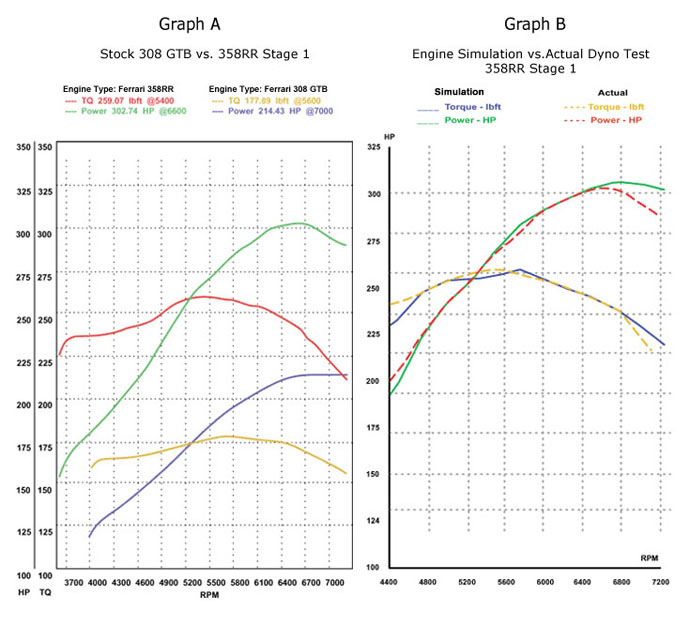
 One item in the simulation that was bothersome had to do with the ignition timing. The standard equipment gives 36°-38° of total advance. The simulation suggested about 28°. To control this, it would be necessary to eliminate the vacuum signal to the ignition and move the pins on the flywheel. We were worried about the possibility of detonation with the higher compression ratio. Adjusting the timing this way had only a small effect on output (1 lbs-ft and 2 HP) so we knew this was the right direction to take. Better safe than very sorry! An analysis of the results is illuminating. In graph "A" we see the comparison of the original baseline test and the final dyno test. The huge improvement is in the torque of the engine; 80 lbs.-ft increase is quite noticeable.
The torque curve stays above 225 lbs.-ft. from 3,600 RPM until 6,900 RPM. Most 308's have about 200 lbs.-ft. peak value. This engine in a 2,800 lbs. car would be thrilling. Moving on to graph "B", we can see the accuracy of the engine simulation model. This is a comparison of the simulation to the actual dyno test. The areas of agreement are from the torque peak to the horsepower peak. The lower RPM area is off (a common result) and after the HP peak the lines diverge. The important point is that we made our HP goal and the idle is dead smooth. This kind of development is not easy and consumes a great deal of time, energy and resources. The result was excellent and all the goals were met. The parts and expertise are now available to do this project again with less brain damage!